


Choosing a servo motor system for a machine design begins with understanding the components that make up the servo motor or servo drive system. Servo systems are closed-loop systems used to control certain desired movements. They include a feedback device that provides constant information between the motor and the driver to precisely control the position, speed, and torque of the mechanism being driven.
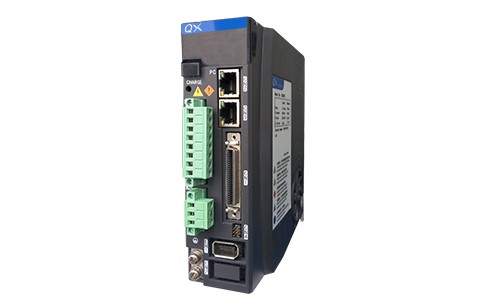
QXR High performance DDR motor servo driver
Typically, servo designs are highly dynamic systems that involve driving a load to accelerate and decelerate rapidly. They operate in four quadrants, which means they can control torque and speed, both positive and negative.
Servo-driven selection requires a systematic solution. In other words, a holistic approach that takes into account overall mechanical, electrical, and programming parameters. The system includes determining mechanical loads, motion curves (including positioning requirements), servo motor characteristics, and the environment in which the motor and other components are located; In particular, when the motor is running at a near constant speed, it has an impact on finished products, materials and/or the process itself.
Mechanical load and motion curve parameters
Let's start by understanding what mechanical load and motion requirements mean. Basic Newtonian physics asserts that force (or torque in the direction of rotation) is proportional to mass (rotational inertia) times acceleration, regardless of whether acceleration is positive or negative. In the context of motion design, machine construction has its own quality and the quality of the load it carries.
Therefore, it is important to determine the mechanical parts - especially the quality of motion and the desired curve of motion. Methods for converting rotational motion into linear motion vary widely and are affected by factors such as accuracy, load, motion dynamics and environment.
Once the mechanism used is understood, understanding the motion dynamics is important to determine the best servomotor solution. The motion curve includes not only the motion from one point to another, but also the functions that may be used in that motion, such as the thrust associated with the machining of the parts. Acceleration, uniform and deceleration, as well as residence and pause times, are all included in the overall motion curve of the system. Indexing moves may be simple triangular motion, variable trapezoid or 1/3-1/3-1/3 (the most efficient motion associated with RMS torque).
Servo system selection and selection tool
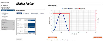
Many vendors offer selection and selection tools to help users build motion profiles based on the motion requirements of their applications. Most software tools, such as Kollmorgen's Motioneering platform, provide a variety of motion descriptions to help you calculate acceleration, movement time, distance, speed, and residence time. Figure 1 shows the basic 1/3-1/3-1/3 curve, with a 50% acceleration introduced to smooth the acceleration. In this example, we chose to move 8 inches in 1 second and use 50% acceleration and a 2 second dwell time. The system calculates motion in terms of 1/3 acceleration time, 1/3 constant velocity, and 1/3 deceleration. The maximum speed calculated by the tool is 720in/min. You can see the "S" curve outline (based on 50% acceleration). In addition, for this motion, it can be seen that a thrust load (red line) is applied to the transverse part of the motion -- this motion curve is probably being machined. Dwell time can also be seen as 3 seconds. The dwell part is important because all the parameters associated with this curve will be used to calculate the RMS torque, which will be a metric we use to select the correct motor. In addition to motion curves, it is also important to understand the actual positioning requirements of loads in terms of resolution, accuracy, and repeatability. This will be directly affected by the selection of feedback devices and (more significantly) by the empty momentum of mechanical fittings in the form of clearance and flexibility.
Unless the design can use a direct drive motor solution, it will include some type of mechanical transmission. Rotating linear power transmission (converting the output of a rotating motor into shaft travel) can be accomplished by pulley drive, or by screw based mechanisms, such as ball screws. The rotary drive includes a gearbox or belt drive assembly so that pulleys of various sizes can be used as retarders. In some applications, the parts being moved contribute significantly to the total motion mass. A special case is the mass of a machine shaft that must be moved to change -- such as in the distribution or processing of a robotic system. The total load variation may be a factor in adjusting the servo drive.
Components in motion must sum their inertia and reflect it back to the motor shaft. In addition to inertia, external forces, friction, and inefficiency must be considered.
Environmental considerations in servo design
It's not over yet. When determining the servo design, only certain available mechanisms can economically and efficiently provide the required motion, carrying capacity, and accuracy. One consideration that is often overlooked is the environment in which the servo system operates. Most servomotors are rated to operate at 40C - a very warm environment, but typical in many factory and industrial Settings.
The heat resistance of the driving electronics is not very high, and since they are also rated at 40 ° C, managing the ambient temperature where they operate is a challenge. Usually, forced cooling in the control cabinet is required to maintain proper environmental conditions (temperature and humidity). Therefore, the location of the motor and driver must be considered. Of course, the motor can be installed or integrated directly into the device to drive the load-carrying mechanism. In contrast, the drive in a centralized solution is located in a control cabinet -- it usually needs to be cooled.
Manufacturers define partial motor performance according to the environmental conditions under which the motor operates. As noted above, many designers assume that the motor is rated for an ambient temperature of 40 ° C, but occasionally a motor specification of 25 ° C is provided. Therefore, attention should be paid to the published reference values when reviewing specifications. If the ambient temperature of the machine exceeds the rated ambient temperature, the motor will not reach the rated power.
Other environmental conditions may affect motor paints and seals and other mechanical subcomponents. Dust, dirt, moisture, spray rinsing, hygiene requirements, explosive environments, vacuum environments, and radiation all require special servomotor with physical characteristics tailored to the current harsh environment.
Selection process
In determining the required motor/drive system composition, a large part of the early selection effort is mechanical and environmental. Now, when the user selects the final product, the remaining system components that the system contains must be considered. Mechanical and environmental factors will continue to influence feedback elements, wiring, and the ultimate choice of control architecture.
Feedback considerations and servo motor characteristics
By definition, servo systems have feedback devices that measure speed, position, and other system parameters during operation. Manufacturers may have limited options, but it is important to carefully consider specific application parameters, including impact load and positioning accuracy as well as repeatability. Rotary transformers often have excellent performance in harsh environments, especially for higher impact loads. A rotating transformer is a rotating transformer consisting of a winding coil with stator and rotor parts around the core. This construction allows for higher temperature operation and greater tolerance to high impact loads than encoders that may contain glass disk elements.
Sinusoidal encoders can provide high resolution, up to 24 bits and beyond, for optimal positioning accuracy. Some hybrid encoders can provide the robustness of a rotating transformer with better resolution. These smart encoders are based on rotating transformers with electronic components that interpret sine and cosine signals and convert them into a high-resolution digital signal that will be passed to a servo driver for use in speed and position feedback.
Currently, the latest encoders offer a variety of communication protocols (EnDAT, BiSS, and DSL) and provide high resolution and low noise capabilities to help achieve optimal feedback signals to servo drivers and controllers.
Another feedback choice that depends on the application requirements is whether you want absolute or incremental feedback. In a rotating system, you can count from 0 once you have completed a 360 degree rotation using a single turn of equipment. The multiturn absolute encoder lets the system know its position, not only the position of the motor in a 360 degree rotation, but also the number of turns it has completed in each direction. So it knows exactly where it is. It is important to know this and where the tools and other axes are located. Simple incremental encoders, on the other hand, can determine the position in a single rotation, but only after finding zero in the power-up cycle. As a result, the user will not know how many cycles have been completed or even the absolute position
in a 360 degree rotation when powered on.
In addition to the servo motor and the servo driver itself, the actual connection between the two is also important. Cable flexibility (defined by its allowable bending radius) is a major consideration, especially when the cable is moving with the shaft.
Cable length may be limited by the type of encoder under consideration. Cable parameters such as impedance and voltage drop, combined with the signal strength of the encoder, are the key factors in length consideration. Some of the newer devices offered on the market transmit serial information to drivers (such as DSL, EnDat, and BiSS) at very high transmission rates, which will be affected by length, especially impedance and signal-to-noise ratio. Even the connector plays a role in the "feedback" loop, as the connector needs to process the various signals generated from these devices. Another cable length factor related to motor power is related to the high switching frequencies involved in today's PWM drivers. There is noise in the power cord of the motor. When the cable becomes longer and approaches half of the frequency wavelength on the cable, an antenna will be formed. The antenna will send or receive information (in this case generating noise) that should not be present in a high performance system.
Last parameter: motion control and network -- centralized versus decentralized
A final consideration that can cause duplication of the overall design process (and change other specified components of the design) is the system architecture. The engineer must ask: Should I focus on a centralized control system with drivers, controllers, and supporting electronics packaged in a centralized cabinet, or is it more profitable and cost-effective to distribute the drivers across the machine (a distributed systems approach)? A machine with multiple axes, which may be scattered across the machine, would be an ideal candidate for a distributed solution. This method can significantly reduce cable requirements and save costs associated with the wiring of long cables and the cable slots and supports that go with these cables. In addition, moving the driver out of the machine reduces the size of the cabinet required to house the control and support electronic components, again reducing costs and cooling requirements within the cabinet. On the other hand, machines that are compact and have fewer axles will not benefit from a traditional
centralized approach.
conclusion
There are many things that must be considered when selecting a servo system for an application, many of which have been described in this article. Another choice that affects the selection of components controls the system. The control type is usually specified at an early stage in machine design discussions and depends on a variety of factors, while the control choice usually locks in the choice of fieldbus communication standards.