
In the PLCopen controller, the coordinate system is the reference point to define the six degrees of freedom (DOFs). Engineers need to understand how different coordinate systems interact and which frames are important for understanding.
Understanding the differences between coordinate systems, and how they interact with each other, is key to achieving successful motion control using groups. In Part 4 of PLCopen, the global standard for IEC6111-3 programmable controller motion control, the concept of multi-axis coordinated motion using groups is introduced. A group is a collection of axes that work together according to a common mechanism to provide a path of motion in three dimensions. Examples include gantry systems, articulated arm robots, triangular robots or connecting mechanisms; Multiple axes work together to achieve multidimensional movement of the device.
As part of the new functionality, the concept of coordinate systems in controllers has become an important topic to understand. The coordinate system is the reference point that defines the six degrees of freedom (DOFs) : X, Y, and Z for Cartesian coordinates, and the Rx, Ru, and Rz angles describing the degree of rotation of each axis (called Euler angles).
Each mechanism, component, or unit of work under control has its own coordinate system. Since the PLCopen controller can control multiple groups, each working on multiple parts, it is important for programmer understanding to recognize how different coordinate systems interact.
Each coordinate system has an origin, which is used to define the zero point in all coordinates. The direction of each axis is determined by the right-hand rule (see Figure 1). If the index finger points in the positive direction of X, the extended middle finger (at a right Angle to the index finger) points in the positive direction of Y, and the extended thumb points in the positive direction of Z.
The Angle direction is determined using the right-hand spiral rule (see Figure 2). The thumb points in the positive direction of the axis, and the finger bends around the axis in the positive rotation direction of the axis.

Position of motor
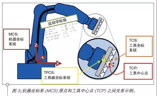
Finally, the controller controls the position of the individual motors. Each axis in the group has its own axis coordinate system (ACS), which is the rotation position of the motor. For most complex mechanisms, such as articulated arm robots, triangulation robots, and connection mechanisms, the position of a single axis coordinate system does not mean that anything is done alone; It is through the coordination of these axes that the position of the machinery is determined using kinematic calculations. These calculations can be performed inside the controller or by a standalone robot controller.
The basic coordinate system for each group is the Machine coordinate system (MCS). The machine manufacturer defines the source of the machine coordinate system. For articulated arm robots and triangular robots, it is usually located on the base of the robot. The controller then performs kinematic calculations to determine the toolboard coordinate system (TPCS), which is the end point of the machine itself. This coordinate system itself is not useful to the programmer, but it can be used to define the origin of the tool location. The knife has its own coordinate system, namely the tool coordinate system (TCS).
Position command
Typically, the tool is centered at the end of the machine, so this may be as simple as an offset in the +Z direction of the toolboard coordinate system, and may also require an Rz component to account for rotation. The tool coordinate system is most commonly used for slow moving and teaching positions, but is not often used in automatic motion. The origin of the tool coordinate system is the tool center point (TCP), which is the starting point of the command displacement. When a shift in the machine coordinate system is invoked, it is the tool center point that moves to that position (see Figure 3).
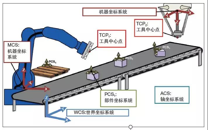
Since each group has its own machine coordinate system origin, moving multiple groups to the same position in space requires each group to have its own position instruction relative to its machine coordinate system position. For example, if two pickup robots pick up items from the same conveyor, then each pickup moves to the same position on the conveyor belt, different machine coordinate system position instructions are required.
To simplify displacement in similar shared Spaces, the origin of the machine coordinate system for each group can be obtained from the origin of the world coordinate system (WCS), plus the offset. Each work unit has only one source of the world coordinate system. When you configure a single group, you need to define an offset to the origin of the world coordinate system. This allows multiple agencies to use a common coordinate system to simplify programming.
The final coordinate system to consider is the component coordinate system (PCS). This coordinate system is used to define the position and orientation of each object in world space. The origin of this coordinate system is located on the part and moves with the part. This is useful when operating on individual parts, such as in a pick-and-place application. Other applications include conveyor tracking, in which components move along a conveyor belt. In this case, the component coordinate system moves relative to the origin of the world coordinate system and the machine coordinate system, so moving the tool center point of the machine to a specific component coordinate system position must take into account the changing offset between the different coordinate systems (see Figure 4).
Understanding the differences between coordinate systems, and how they interact with each other, is key to successful motion control using groups in the IEC. Different coordinate systems work together to accomplish the desired operation.
Example of conveyor belt tracking
In a conveyor belt tracking application, the first command may be to move the tool center point in the machine coordinate system to locate the tool center point to the initial position of the tracking area. The position and orientation of the part are defined, and the transmitter tracking routine calculates the offset of the part to the origin of the coordinate system of the mechanism machine. This offset defines the component coordinate system of the part and the relationship between the machine coordinate system and the tracking function of the conveyor. The offset of the component coordinate system is adjusted as the part moves. The user then defines a move in the part coordinate system space to pick up the part. Since the component coordinate system offset has 6 degrees of freedom, opening the box on the conveyor belt can also be achieved if necessary. The user then performs a displacement in the part coordinate system space to pick up the part.
The tool orientation is automatically matched to the part (if needed), and the offset between the coordinate systems has taken these factors into account. The same part coordinate system position is used for each pickup, and the part coordinate system offset changes only when a new part is encountered. Since the conveyor belt tracking function constantly updates the offset of the component coordinate system, the tool center point is also tracked along the positive direction of the conveyor belt to solve the component movement problem.